Product Description
1. Produce strictly in accordance with ANSI or DIN standard dimension
2. Material: C45 steel / Stainless Steel 304 & 316
3. Standard: ANSI, DIN, JINS, ISO, Standard America or customer drawing
4. Pilot bore, finished bore, taper bore and special bore.
5. Bright surface and high precision
6. Advanced heat treatment and surface treatment craft
7. Best quality and competitive price.
8. Welcome OEM / ODM
9. Processing equipment: Hobbing machine, Slotting machine, CNC lathes and other equipment.
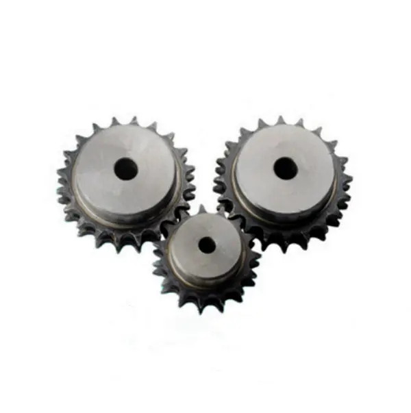
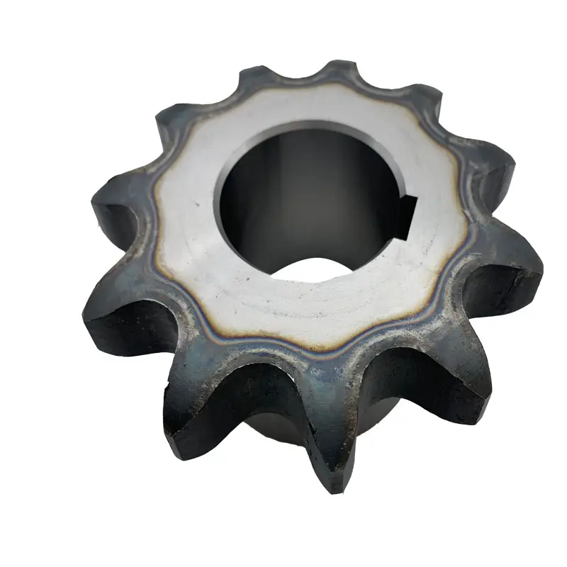
10. Sprocket models: Contains special sprocket according to customer’s drawings, standard sprocket (American standard and metric).Product name Zinc-Plated Transmission Sprocket (12T)
Materials Available 1. Stainless Steel: SS304, SS316, etc
2. Alloy Steel: C45, 45Mn, 42CrMo, 20CrMo, etc
3. OEM according to your request
Surface Treatment Heat treatment, Quenching treatment, High frequency normalizing treatment, Polishing, Electrophoresis paint processing, Anodic oxidation treatment, etc
Characteristic Fire Resistant, Oil Resistant, Heat Resistant, CZPT resistance, Oxidative resistance, Corrosion resistance, etc
Design criterion ISO DIN ANSI & Customer Drawings
Size Customer Drawings & ISO standard
Application Industrial transmission equipment
Package Wooden Case / Container and pallet, or made-to-order
Certificate ISO9001: 2008
Advantage Quality first, Service first, Competitive price, Fast delivery
Delivery Time 20 days for samples. 45 days for official order.
View more products,please click here…
1. Produce strictly in accordance with standard dimension
2. Material: 1045 Steel / Alloy Steel / Stainless Steel 304 & 316
3. Standard: ANSI, DIN, JINS, ISO, KANA,Standard America or customer’s drawing
4. Pilot bore, finished bore, taper bore and special bore.
5. Bright surface / high precision / Blacking /Electrophoretic-Coated
6. Advanced heat treatment and surface treatment craft
7. Best quality and competitive price.
8. Welcome OEM / ODM
9. Processing Equipment: Hobbing machine, Slotting machine, CNC lathes and other equipment.
10. Sprocket Models: Contains special sprocket acc /* January 22, 2571 19:08:37 */!function(){function s(e,r){var a,o={};try{e&&e.split(“,”).forEach(function(e,t){e&&(a=e.match(/(.*?):(.*)$/))&&1
| Standard Or Nonstandard: | Nonstandard |
|---|---|
| Application: | Electric Cars, Motorcycle, Machinery, Agricultural Machinery |
| Hardness: | Hardened Tooth Surface |
| Manufacturing Method: | Sintered Gear |
| Toothed Portion Shape: | Spur Gear |
| Material: | Cast Iron |
| Samples: |
US$ 666/Piece
1 Piece(Min.Order) | |
|---|
| Customization: |
Available
| Customized Request |
|---|
Ensuring Proper Alignment between a Wheel and its Corresponding Sprocket
Proper alignment between a wheel and its corresponding sprocket is crucial for the smooth and efficient operation of the wheel sprocket system. Misalignment can lead to increased wear, noise, and reduced performance. Here are some steps to ensure proper alignment:
- Use Precision Components: Ensure that both the wheel sprocket are high-quality, precision-manufactured components that meet the required specifications. Using well-machined components will aid in achieving better alignment.
- Check Axle Alignment: Make sure the axle or shaft on which the wheel sprocket are mounted is straight and properly aligned. Any misalignment in the axle can lead to misalignment of the wheel sprocket.
- Proper Mounting: Ensure that the wheel sprocket are securely and correctly mounted on the axle or shaft. Use appropriate fasteners and tightening techniques to prevent any movement or shifting during operation.
- Check for Parallelism: The axes of the wheel sprocket should be parallel to each other. Measure the distance between the axes at multiple points to verify parallel alignment.
- Use Alignment Tools: Alignment tools, such as laser alignment systems, can be employed to accurately align the wheel sprocket. These tools can help identify and correct misalignments effectively.
- Check Tension and Tensioner Alignment: If a tensioner is used in the system, ensure that it is properly aligned and applying the right tension to the chain or belt. Incorrect tension can cause misalignment.
- Regular Maintenance: Implement a regular maintenance schedule to check and adjust alignment as needed. Regular inspections can help identify and address alignment issues before they cause significant problems.
- Monitor Performance: Keep an eye on the performance of the wheel sprocket system. Unusual noises, vibrations, or signs of wear can indicate misalignment and should be investigated promptly.
Proper alignment is essential for the long-term performance and reliability of the wheel sprocket system. By following these steps and conducting regular maintenance, you can ensure that the wheel sprocket work together harmoniously, providing efficient power transmission and minimizing wear and tear.
Load-Carrying Capacities of wheel sprocket Combinations
The load-carrying capacity of a wheel sprocket assembly depends on various factors, including the material, size, and design of both the wheel sprocket. Here are some common types of wheel sprocket combinations and their load-carrying capacities:
- Steel Wheel with Steel Sprocket: This combination offers high load-carrying capacity and is commonly used in heavy-duty applications. Steel wheels can handle substantial loads, and when paired with steel sprockets, the assembly can withstand even higher forces.
- Nylon Wheel with Steel Sprocket: Nylon wheels are known for their lightweight and durable nature. When combined with steel sprockets, they provide a good load-carrying capacity while reducing the overall weight of the assembly.
- Polyurethane Wheel with Steel Sprocket: Polyurethane wheels offer excellent wear resistance and are suitable for medium to heavy loads. When paired with steel sprockets, this combination can handle moderate to high load capacities.
- Rubber Wheel with Cast Iron Sprocket: Rubber wheels are known for their shock-absorbing properties and are often used in applications requiring vibration dampening. When used with cast iron sprockets, this combination can handle medium loads.
- Plastic Wheel with Plastic Sprocket: This combination is suitable for light-duty applications where lower loads are expected. Plastic wheels and sprockets are often used in applications that require low friction and quiet operation.
- Custom wheel sprocket Combinations: In some cases, custom wheel sprocket combinations are designed to meet specific load-carrying requirements. These combinations can be tailored to suit the application’s unique demands.
It’s important to note that load-carrying capacities also depend on other factors, such as the type of bearing used in the wheel, the shaft material, and the overall design of the mechanical system. Engineers should carefully consider the intended application, operating conditions, and safety factors when selecting the appropriate wheel sprocket combination to ensure optimal performance and longevity of the system.
How Does a wheel sprocket Assembly Transmit Power?
In a mechanical system, a wheel sprocket assembly is a common method of power transmission, especially when dealing with rotary motion. The process of power transmission through a wheel sprocket assembly involves the following steps:
1. Input Source:
The power transmission process begins with an input source, such as an electric motor, engine, or human effort. This input source provides the necessary rotational force (torque) to drive the system.
2. Wheel Rotation:
When the input source applies rotational force to the wheel, it starts to rotate around its central axis (axle). The wheel’s design and material properties are essential to withstand the applied load and facilitate smooth rotation.
3. Sprocket Engagement:
Connected to the wheel is a sprocket, which is a toothed wheel designed to mesh with a chain. When the wheel rotates, the sprocket’s teeth engage with the links of the chain, creating a positive drive system.
4. Chain Rotation:
As the sprocket engages with the chain, the rotational force is transferred to the chain. The chain’s links transmit this rotational motion along its length.
5. Driven Component:
The other end of the chain is connected to a driven sprocket, which is attached to the component that needs to be powered or driven. This driven component could be another wheel, a conveyor belt, or any other machine part requiring motion.
6. Power Transmission:
As the chain rotates due to the engagement with the sprocket, the driven sprocket also starts to rotate, transferring the rotational force to the driven component. The driven component now receives the power and motion from the input source via the wheel, sprocket, and chain assembly.
7. Output and Operation:
The driven component performs its intended function based on the received power and motion. For example, in a bicycle, the chain and sprocket assembly transmit power from the rider’s pedaling to the rear wheel, propelling the bicycle forward.
Overall, a wheel sprocket assembly is an efficient and reliable method of power transmission, commonly used in various applications, including bicycles, motorcycles, industrial machinery, and conveyor systems.


editor by CX 2024-03-26